
Connecting the Coapt system components
The Coapt system is a stand-alone prosthesis control system. Its inputs are EMG signals from the user and its outputs are commands to the prosthesis. This section will guide you through connecting the EMG inputs cable and the prosthesis connection cable to the Coapt main controller unit.
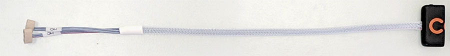
The main processing unit of the Coapt system is the Complete Controller. Permanently attached to that is the Complete Calibrate button. That button is designed to be secured into the outer socket wall of the prosthesis with its button side exposed to the user. You can make good use of the provided fabrication aids to ensure the Complete Controller and the Complete Calibrate button fit perfectly.
DOWNLOAD THE PRODUCT HANDBOOK FOR DETAILED COMPONENTS & FABRICATION INFORMATION
The Complete Controller main unit arrives in its box with two cables already attached. One should have white sleeving and the other gray sleeving. If you haven’t already, feel free to detach those cables for easier fabrication. The logo on one side and some instructive arrows on the other side will help you make sure you will reattach them correctly. These are unique and keyed connectors which also helps.
Connect the gray jacketed cable.
This is the EMG Interface Cable. One end of this cable has a wide connector that mates with the Complete Controller while the other end will be your EMG interface of choice; e.g. a set of ring-terminal eyelets, snap connectors, or perhaps even an EMG cuff. In most assemblies, it will make sense to attach the EMG interface end to Dome Electrodes mounted in the socket/liner first.
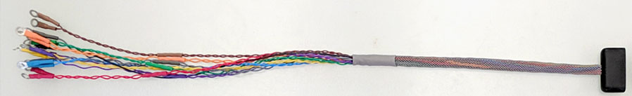
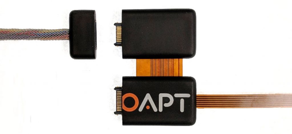
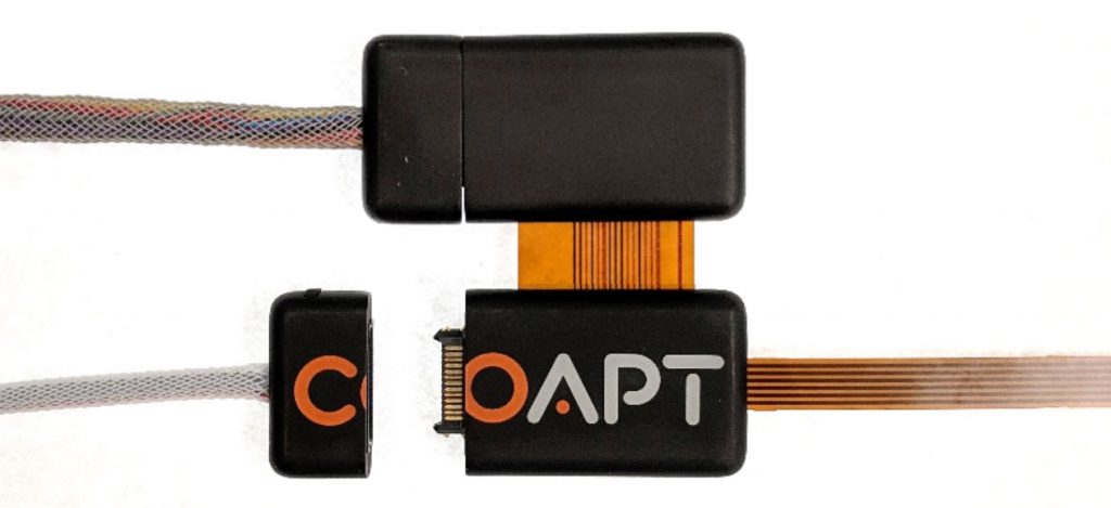
To connect the EMG Interface Cable to the controller, line up the arrows on the bottom labels that point directly at each other and push the connector on until it clicks in place. Note there are NO logo parts printed on the EMG Interface Cable connector nor the EMG connection half of the Complete Controller.
Connect the white jacketed cable.
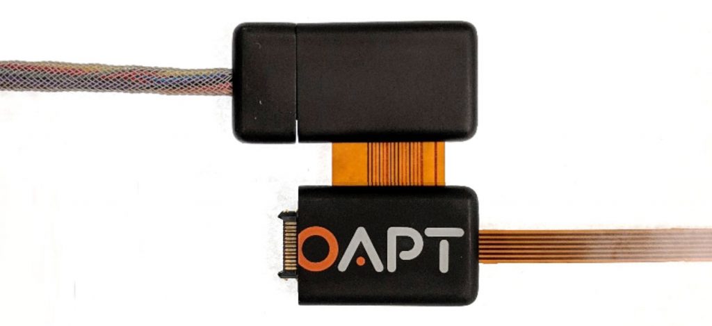
This is the Device Interface Cable. The Device Interface Cable connects the Complete Controller to the prosthetic device(s) being controlled. One end of this cable has a wide connector that mates with the Complete Controller while the other end has variable termination for connection to the prosthetic device(s) being controlled. These varied connectors are specifically tailored to your specified prosthetic configuration and are identified by a Cable Type code on the label of the Device Interface Cable. Refer to the visual connection guides for each different cable type available on this website, or the same visual instructions in the Coapt software applications. Please contact a Coapt representative for assistance if you are not comfortable making any of the connections to the prosthetic components.
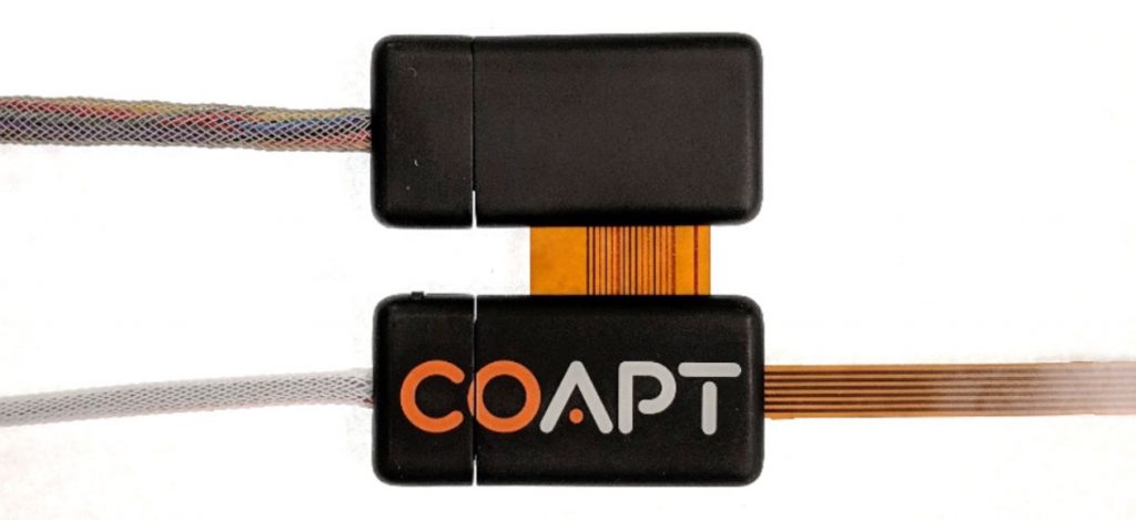
To connect the Device Interface Cable to the controller, line up the arrows on the bottom labels that point directly at each other and push the connector on until it clicks in place. Coapt logo halves printed on the Device Interface Cable connector and the device connection of the Complete Controller will combine to complete the logo when properly connected.
Don’t forget, the Device Interface Cable is how the Complete Controller receives power. Batteries already incorporated in the prosthesis will supply switched power through the Device Interface Cable. When you are ready to test that proper connections of the Device Interface Cable to the prosthetic devices are made, use the “Manual Test” section in the Coapt software application.