
Getting the most out of Coapt’s user interface software and app
Complete ControlRoom is an easy-to-use and convenient user interface application available to both clinicians and users. It can be downloaded and installed as a PC application or found in the Apple store and Google Play as a mobile app.
Installation
Windows PC
- Download the Complete ControlRoom to save the installer application file to the computer.
- Navigate to the downloaded installer application file and double-click to begin.
- Follow the install wizard directions.
- Once the installation is complete, click on the desktop icon to use the Complete ControlRoom application software as needed.
iOS
- On an iOS device, visit the App Store (To install apps, sign in with an Apple ID or create one).
- Search for the Coapt Complete ControlRoom application by name.
- Tap the app.
- Tap GET then tap INSTALL.
ANDROID
- On an Android device, visit the Google Play Store.
- Search for Coapt Control Companion.
- Tap the app.
- Tap INSTALL.
Updates
Windows PC
The Complete ControlRoom application will alert you when a critical update is available.
- A pop-up window will ask if you want to install – select yes.
- The update procedure will be initiated and will restart the Complete ControlRoom application when complete.
ANDROID
When an update is available for the Complete ControlRoom application, the Android device should automatically initiate the update when the application is opened.
Android applications can also be updated manually:
- From the Play Store Home screen, tap your Google profile icon (upper-right).
- Tap My apps & device.
- Tap individual installed apps to update or tap Update All to download all available updates.
- If presented, review App Permissions then tap Accept to proceed with app update.
iOS
When an update is available for the Complete ControlRoom application, the iOS device should automatically initiate the update when the application is opened.
- From the Home screen, tap App Store
 .
. - Tap Updates in the bottom right corner.
- Find Complete ControlRoom application and tap the Update button next to it.
Complete ControlRoom Gen 2 Environments
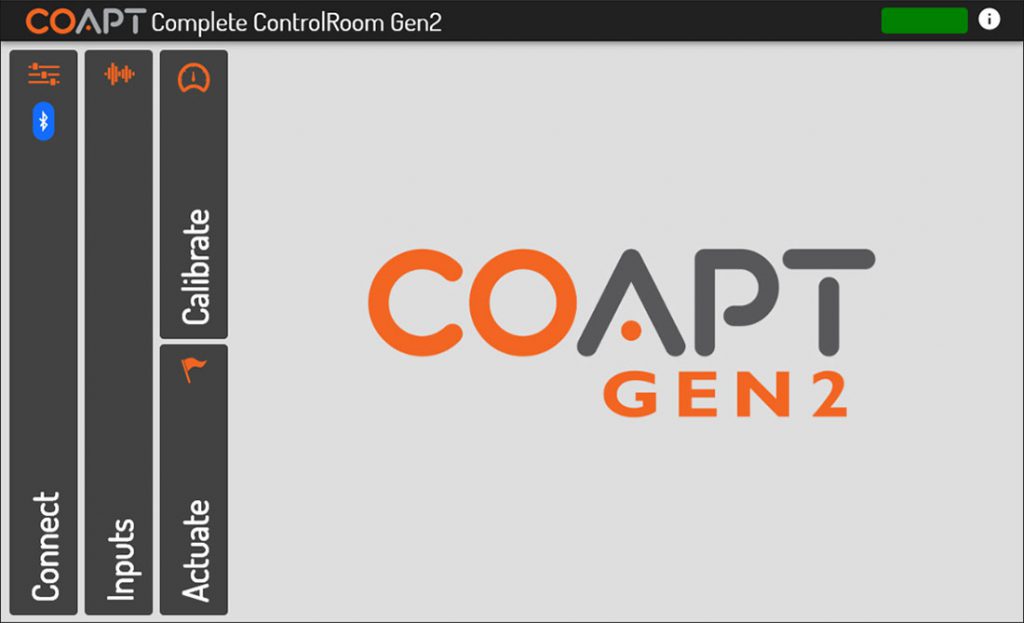
Dashboard
The Dashboard environment appears when Complete ControlRoom is launched and presents navigation to the four other Complete ControlRoom environments.
Connect
The Connect environment has two main purposes:
- Manage Bluetooth connection to a Complete Controller System Gen2.
- Guide the correct configuration and physical connections of the Complete Controller System Gen2 to the prosthesis.
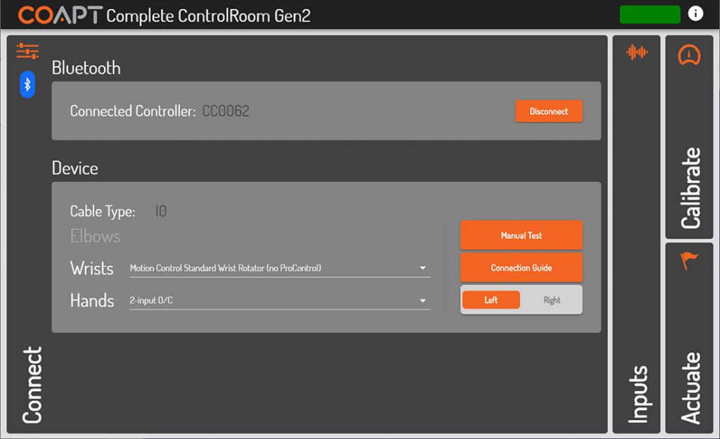
More about Connect panel elements (Bluetooth sub-panel)
| CONNECTED CONTROLLER | A Bluetooth-connected Complete Controller will be named by its serial number starting with “CC”. Check the serial number displayed on the screen and the serial number of the device (located on its label) to ensure you are connected to the correct Complete Controller. |
| SCAN/DISCONNECT – BUTTON | Displays a list of any Complete Controller devices currently broadcasting over Bluetooth. Clicking on the serial number identifier of one will establish Bluetooth connection. This button changes to “Disconnect” once Bluetooth connection has been established to a device. Clicking on “Disconnect” will terminate the Bluetooth connection. |
After a period of inactive Bluetooth communication (e.g. being disconnected from the software application), a Complete Controller will stop radio broadcasting in order to save battery power. To have the Complete Controller turn its Bluetooth capabilities back on, simply press the Complete Calibrate button once quickly or turn the power of the prosthesis off and then back on.
More about Connect panel elements (Device sub-panel)
| CABLE TYPE | When Complete ControlRoom establishes Bluetooth connection to a Complete Controller, the type of Device Interface Cable attached is detected and displayed. The Cable Type is a two-character code that will match the labelling on the Device Interface Cable. |
| ELBOWS/WRISTS/HANDS | Each unique Cable Type determines the set of pull-down menus and their contents. Available options represent the known possible devices compatible with that particular Device Interface Cable. Take care to select their prosthetic devices accordingly. |
| MANUAL TEST – BUTTON | Opens a pop-up window where all available prosthesis actions/functions will be listed on individual buttons. Clicking and holding on any of these buttons is intended to result in the corresponding prosthesis action. Direction flipping/reversing is also available. |
| CONNECTION GUIDE – BUTTON | Opens a pop-up window that displays helpful information for proper physical connection of the Device Interface Cable to the prosthetic devices as well as other devices’ suggested software settings (where applicable). |
| LEFT/RIGHT – TOGGLE | Selects either left-handed or right-handed prosthetic device and virtual arm operation. |
Manual test is provided to ensure proper operation, connection, and configuration of the prosthetic device(s) has been made. If proper setup with prosthetic devices is not complete, the Complete Control System Gen2 will not be able to function at its ideal capacity.
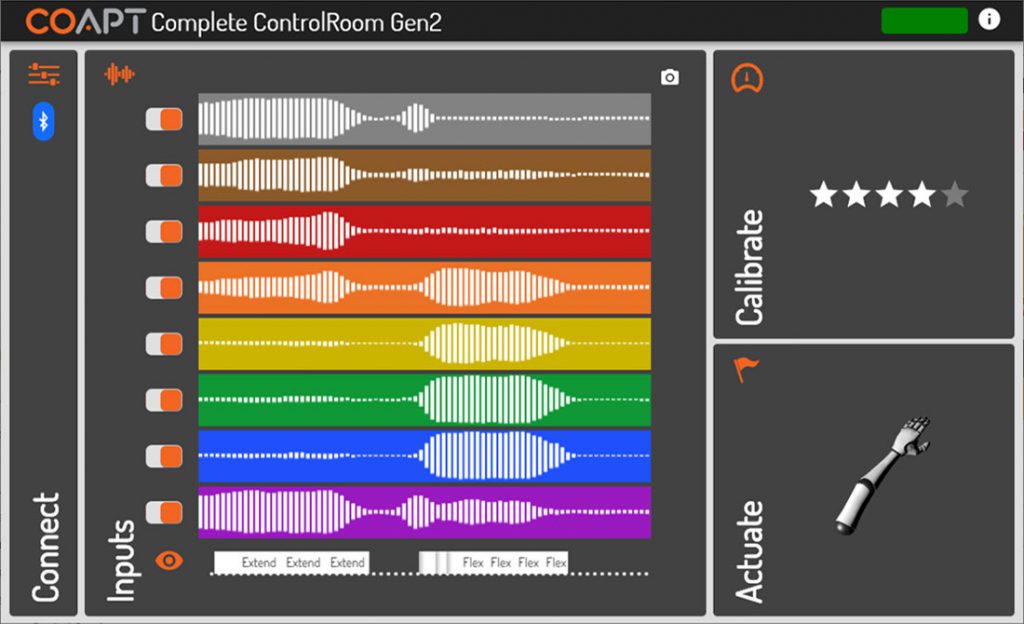
Inputs
The Inputs environment has three main purposes:
- Verification that EMG inputs have reliable electrode-to-skin contact
- Allowing for on/off toggle of EMG input channels for diagnostic purposes
- Display a real-time classification output (when calibrated) corresponding to inputs’ patterns
The Complete Control System Gen2 is designed to function at its ideal capacity with all eight EMG channel inputs. Any EMG channels that are turned off should be corrected to ensure reliable electrode contact and then turned back on for optimal performance.
More about Inputs panel elements
| EMG INPUT BARS | Dynamic signal activity on eight horizontal bars of color represent the eight EMG channel inputs of the Complete Control System Gen2. The on-screen colors correspond to the EMG wire colors of the EMG Interface Cable. A real-time signal quality assistant monitors for EMG electrodes losing contact with user’s skin (“lift-off”). When lift-off is detected, a warning message is displayed on the corresponding signal channel. |
| EMG INPUTS – ON/OFF TOGGLES | Each EMG Input channel has an on/off toggle that will determine its inclusion or exclusion from the set of pattern recognition inputs. It is strongly suggested that all eight EMG inputs are used to ensure optimal performance. |
| SCROLLING OUTPUTS DISPLAY | Below the set of EMG inputs is a scrolling display that shows real-time control outputs from the current state of the Complete Control system’s calibrated pattern recognition classifier. No motions will be displayed when the system is in a Reset state. For convenience, visibility of this output display can be toggled on or off by clicking the “eye” icon. |
| SNAPSHOT – BUTTON (CAMERA ICON) | The camera icon opens a pop-up window that contains a snapshot of the EMG Inputs activity at the moment the button was pushed. The pop-up allows for the captured imaged to be saved for later use. |
Calibrate
The Calibrate environment assists the user with calibration of their Complete Control System Gen2.
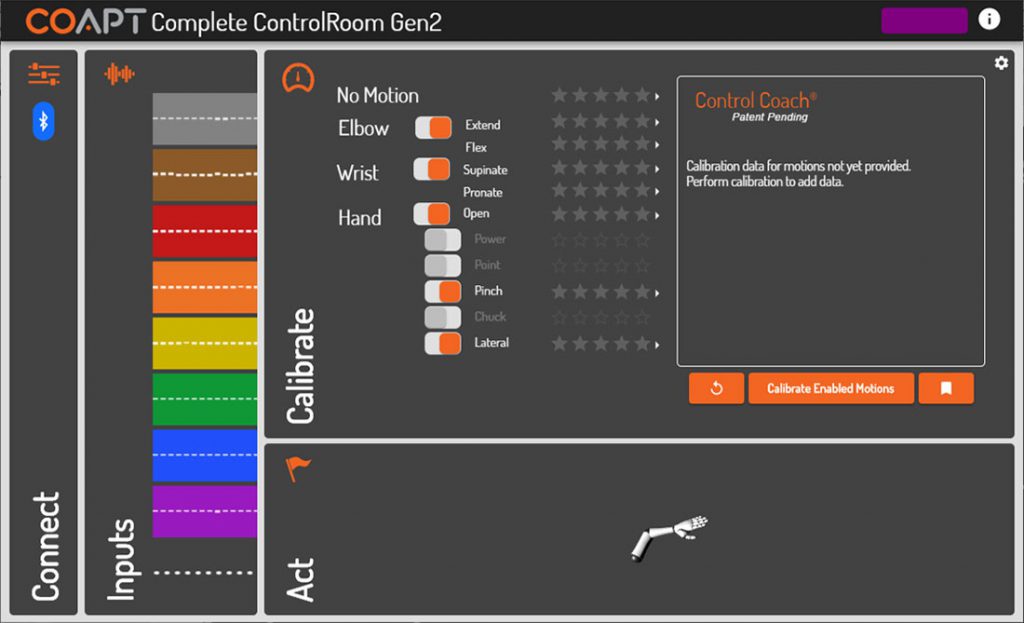
More about Calibrate panel elements
| ACTION/FUNCTION TOGGLES | Allows selection of which actions/functions are included in calibration for prosthetic control. |
| ACTION/FUNCTION STAR RATINGS | Displays the A.I. Control Coach® estimated calibration quality for each action/function (see Control Coach® section for more). |
| ACTION/FUNCTION CONTROL COACH® ARROWS | Clicking the arrow next to any action/function will expand its specific Control Coach® information in the Control Coach® sub-panel (see Control Coach® section for more). |
| CALIBRATE ENABLED MOTIONS – BUTTON | Initiates the guided calibration sequence of all of the actions/functions toggled on. |
| UNDO – BUTTON (COUNTER-CLOCKWISE ARROW ICON) | Reverts the system to the calibrated state it was in just before the most recent calibration activity, that activity either being single-motion or full-sequence calibration. The Undo functionality only applies to one calibration step; that is, undoing more than one calibration step is not possible. |
| RESTORE POINTS – BUTTON (BOOKMARK ICON) | Opens a pop-up window for storing or loading a Calibration Restore Point. |
| SETTINGS – MENU (COGWHEEL ICON) | Opens a pop-up window for Complete Control calibration settings: |
| CALIBRATION PACE – SELECTOR | Sets the pace at which prompts will be spaced during a calibration sequence. |
| ADAPTIVE ADVANCE™ – TOGGLE | When “On” (default), enables the Adaptive Advance™ continuous-learning algorithms to meld any new calibration data into the existing state of users’ control (see Adaptive Advance™ section for more). |
| CONTROL COACH® LED SENSITIVITY – SELECTOR | Adjusts when the Control Coach® white LED on the Complete Calibrate button will come on. For example, when set to 2 stars, the Complete Calibrate button indicator will only come on when the overall Control Coach® star rating is a 2 or less (see Control Coach® section for more). |
| SINGLE-CLASS CALIBRATION DATA AMOUNT – SLIDER | Determines how much calibration data users will be tasked to provide in order to “fill-the-bucket” during any Single Class Calibrations. |
| RESET ALL – BUTTON | Sets the Complete Control system to a blank starting state. The control memory will be emptied and will need at least one new calibration to actuate the prosthesis. |
Actuate
The Actuate environment assists the user with on-screen prosthesis control practice using their Complete Control System Gen2.
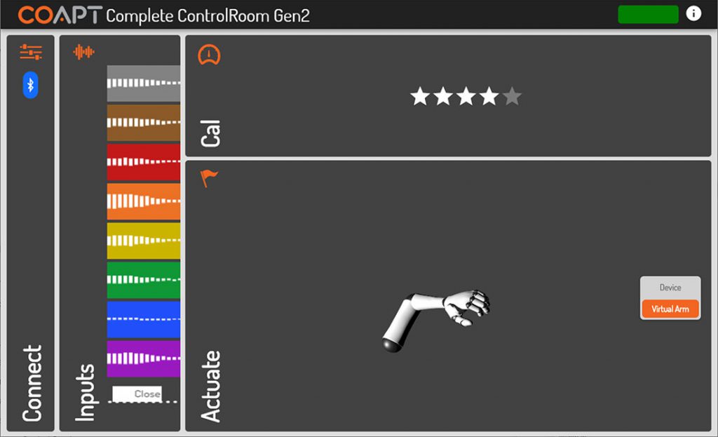
More about Actuate panel elements
| VIRTUAL ARM/DEVICE – TOGGLE | Allows the user to direct their real-time pattern recognition control to either the on-screen arm or their prosthesis. |